Tools and Utilities
Manual Guide
Auto-Select Star
Calibration Details
PHD2 Server
Dithering Operations
Logging and Debug Output
Drift Alignment
Lock Positions
Comet Tracking
Guiding Assistant
Equipment Profiles
Simulator Parameters
Keyboard Shortcuts
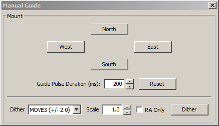
Manual Guide
If you are connecting to a new mount and are encountering calibration
problems, you will probably want to be sure that PHD2's
commands are
actually getting to the mount. Or you may want to nudge the mount or
experiment with manual dithering. In the 'Tools' menu, click on
'Manual
Guide' and
a dialog will appear to let you move the mount at guide speed in any
direction. If you have an
adaptive optics device attached, you'll see separate move buttons for
both the AO and the secondary mount. Each time you press the button, a pulse of the duration
specified in the 'Guide Pulse Duration' field will
be sent. The default value is the 'calibration step-sze' set in
the Advanced Options dialog. If you are debugging mount/calibration
problems in the daytime, listen to (rather than watch) your mount to determine if it is getting
the commands from PHD2. The idea here is just to figure out if the
mount is responding
to PHD2's
signals. You won't be able to see the mount move (it's moving
at guide speed)
but you may be able to hear the motors. Other options include watching
the
motors and gears or
attaching a laser pointer to your scope and aiming it at something
fairly far away (to amplify your motions). A better approach
for nighttime testing is to run the "star-cross" test described here.
Dithering
is used primarily with image capture or automation applications through the PHD2 server interface. However, you can do
manual dithering or experiment with dither settings using the controls
at the bottom of the dialog. The 'dither' amount field at the
left controls the amount the mount will be moved , in units of
pixels. You can scale this amount - i.e. multiply it by a
constant - by using the 'scale' spin control to the right. These
two controls establish a maximum amount of movement that will be used
for dithering - the product of 'scale' X 'dither'. When you click
on the 'Dither' button, PHD2 will move the mount by a random amount
that is less than or equal to the limit you have set, in one of the
north/south/east/west directions. The 'RA Only' checkbox will
constrain the dither adjustments to only east or west. Obviously,
if you are doing a manual dither in this way, you'll want to be sure
your imaging camera is not in the middle of an exposure.
Auto-Select Star
Clicking on 'Auto-select Star' under the 'Tools' menu, or using the keyboard
shortcut of <Alt>S, tells PHD2 to scan the current guide image
and identify a star suitable for guiding. PHD2 will try to select a star of sufficient brightness that is not
near another star and not too close to the edge of the frame. The
selected star may appear overly dim on the screen, but this is usually
not a problem. You can use the Star Profile tool
to examine the properties of the selected star - it should be
non-saturated with a sharp profile, the same properties you should look
for when choosing a guide star manually. The auto-select process is not
infallible, so you may need to select a star yourself if you don't like
the automated result. If you want to use Auto-Select, you should
definitely use either a bad-pixel map or dark library to reduce the
likelihood of PHD2 mistakenly choosing a hot pixel.
Calibration Details
Most of the calibration-related windows, including calibration sanity-checks, will open a window that looks something like this:
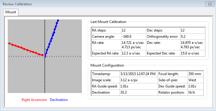
The
first thing to look at is the graph to the left, which shows what star
movements resulted from the guide pulses that PHD2 sent during
calibration. The lines represent the RA and Dec guide rates that
were computed as a result of the calibration, and these lines should be
roughly perpendicular. The data points will never be perfectly
aligned, but they should not have major curves, sharp inflections,
or reversals in direction. Particularly with longer focal length scopes, the
points will often show considerable scatter around the lines, but this
is normal. The solid points (west and north pulses) are used to
compute the RA and declination rates, while the hollow points show the
"return" paths of the east and south moves. These can help you
see how much fluctuation occurred due to seeing and also whether there
is a significant amount of backlash. If you are using the
"fast-recenter" option in the Advanced Settings, there may be many
fewer points shown in the east and north paths. The tabular
information to the right
shows what was known about the pointing position of the scope and the
various ASCOM settings that relate to guiding. If you are not
using an ASCOM mount and don't have an "Aux mount" specified, some of
this information will be missing. The table will also show
the expected guiding rates for a "perfect" calibration using
the same sky position and guide speed settings you used. You will
almost never achieve these ideal values, and you shouldn't worry about
them unless your values are very different. If you didn't see an
alert message when the calibration completed, your results are probably
good enough. If you want to re-use a calibration for an extended
time, it is probably worth a few extra minutes to check this
information and confirm that the calibration went
reasonably well and produced sensible results. Bad calibrations
can occur even for very experienced imagers using high-end mounts, so
it is good to check.
Declination Backlash
A common source of calibration problems is declination
backlash, which is present to some degree in most geared mounts.
With some mounts, however, the problem can be severe and
can lead to poor calibration and guiding results. Consider the following
calibration review dialog:
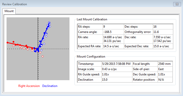
The
first clue to the problem is found by comparing the declination and
right ascension guide rates. In this case, the declination rate
is barely 1/2 of the RA rate, something that should never occur.
In fact, this would have triggered a calibration alert dialog.
Now look at the graph of the declination points, in blue, and
notice the clumping of points near the zero-point of the graph.
Although a total of 16 steps were taken in declination, only the
last 9 were actually moving the mount in a consistent way - the first 7
basically accomplished nothing because of backlash. There are
actually two problems to be addressed here. First, the
calibration result is poor and should be repeated in order to get a
more accurate measure of the declination guide rate. Second, the
mount is likely to behave badly during direction reversals in
declination even if the dec guide rate is correct. The
calibration can be improved by first manually moving the mount
north at
guide speed for 10-20 seconds until consistent star
movement is seen in the main window. You can do this with
the 'Manual Guide'
tool or by using the hand-controller on your mount. Once this is
done, most of the declination backlash in your mount should have been
overcome. You can then repeat the calibration procedure
and probably get a declination guiding rate that is more
reasonable.
The second problem generally requires some mechanical adjustment
to the mount. You can try using a backlash compensation setting,
but this is not likely to work well if the backlash is large -
more than 2-3 seconds, for example. If you can't correct
the
backlash or reduce
it to manageable levels, you should consider choosing uni-directional
guiding for declination. To do this, you determine
which way the mount drifts due to polar alignment error, and tell PHD2
to guide only in the opposite direction. For example, if the
mount tends to drift north overall, restrict guide commands to
south-only. This is not an ideal solution, obviously, but you can
still use reasonably long exposures and achieve decent guiding results
- and there are plenty of imagers out there who use this technique.
Other Calibration-Related Menu Options
Calibration data are saved automatically each time a calibration sequence completes
successfully. The use of the calibration data has been described
elsewhere (Using PHD Guiding),
including options for restoring calibration data from an earlier
time or "flipping" it after a meridian flip. You access these
functions using the 'Modify Calibration' sub-menu under the 'Tools' menu. Two other
calibration-related items are shown there, namely the options to
clear the current data or to enter calibration data manually. The
"clear" option accomplishes the same thing as the 'Clear calibration'
checkbox in the Advanced Dialog - it will force a recalibration
whenever guiding is resumed. The 'Enter calibration data'
option should be used only under
very unusual circumstances and only if you're sure you know what you're
doing; but it is available as a matter of completeness. If you
click on the 'Enter calibration data' item, you'll see a dialog box
that allows input of relatively low-level calibration data. This
data might come from a much earlier session, perhaps extracted from the
PHD2 guiding log file.
Keep in mind, if you are using an ASCOM driver for either the
'mount' or 'aux mount' connections, you should have little need for
these calibration data controls.
PHD2 Server
PHD2 supports third-party imaging and automation applications that need to control the guiding process. Stark Labs' Nebulosity program
was the first to do this, but other applications have subsequently been
produced. By using the PHD2 server process, image capture
programs can control dithering between exposures or suspend guide
exposures while the primary imaging camera is downloading data.
To use these capabilities with a compatible application, you
should click on the 'Enable Server' option under the 'Tools'
menu. The server interface has been reworked substantially in
PHD2, and it's now possible
for an application to control most aspects of PHD2's guiding operations. Documentation for the
server API is available on
the PHD2
Wiki.
Dithering
The primary purpose of dithering is
to make post-processing easier by removing some kinds of fixed-pattern
noise in the images, especially hot pixels. This is almost purely
a function of the camera you're using and to a lesser extent, the
sophistication of the post-processing software. For imagers
with temperature-regulated, low-noise cameras, dithering is mostly
a convenient way to eliminate hot pixels that aren't getting
removed by the dark frames. Hot pixel positions change as sensors
age, so dark libraries don't usually correct for all of them. Those hot
pixels can also be also removed in post-processing, but that becomes
tedious if there are lots of them. It's also possible that
dithering can help with some other kinds of sensor behavior such as
column defects, and it's particularly helpful if there is no
temperature regulation on the sensor and therefore no good way to use a
dark library. DSLR imagers often use aggressive dithering for
those reasons. In the PHD2 implementation, automated
dithering is accomplished through the server interface, so make sure
you have 'Enable Server' checked under the 'Tools' menu. You
first specify a maximum dither size you want to use during the
guiding session - this will be set in your imaging application.. Then,
when that application issues a dither command, PHD2
uses a random number generator to decide how large the dither will
actually be for that command. The actual dither mount will be
> 0
and <= the maximum amount allowed. You want to use pseudo-random
dither amounts like this to be sure that dithering doesn't follow a
consistent pattern or shift the frame back to a location where it has
previously been. But for some of the applications that do PHD2
dithering, you
can't specify the maximum amount directly - you are perhaps limited to
choices like small/medium/large and the max dither amounts will have
preset values. For that reason, PHD2 has a dither scaling
parameter in the 'Global' tab of the Brain dialog. It is
basically a multiplier term that lets you adjust the range of dither
amounts that are possible. So a scale factor of 1 doesn't change
the
preset value at all, a value of 10 multiplies it by 10X, etc. If
you're using an app that lets you specify the maximum amount directly
(e.g. PHD_Dither), you should leave the dither scale set to 1.0.
Otherwise, you can adjust the scale factor if you aren't
happy with the overall range of dithering you're getting with one of
the small/medium/large type imaging apps.
There are typically
two costs associated with dithering: 1) the extra time and uncertainty
required for "settling" and 2) the need to crop the final stacked frame
in order to remove the low-signal margins. Settling is the term
used for a period of stabilization after the mount has been moved by a
dither command. The imaging app that starts the dither will also
decide when the guiding has stabilized enough to continue
imaging. The app can let PHD2 determine this by specifying the
settling parameters or the app can do the calculations itself.
You'll need to look at your imaging/dithering app to see what control
you have over this process. If the app uses the latest PHD2
server interfaces, it can specify a settling requirement that might
look like "guiding errors must be less than 1.5 pixels for a period of
at least 10 seconds." This is a process that can consume some
time, depending on how tight the requirements are for settling.
It is likely to take more time if you are dithering in declination and
the dither forces a change in direction. Most mounts have some
declination backlash, so it can take a number of guide commands to get
the mount moving in the right direction, and then more time for the
process to converge on the new target location for the guide
star. That's why PHD2 also offers the option to dither only in
right ascension. Again, this is an option on the 'Global' tab,
right next to the dither scaling parameter.
Logging and Debug Output
PHD2 automatically creates two types of log files: a debug log and a
guiding log. Both are very useful for different reasons.
The guiding log is similar to the one produced by PHD, but
with
extended information. The guide log is intentionally formatted to
allow easy interpretation by either a human reader or an external
application. For example, the very capable PHDLogView application (not
part of the PHD2 release) can produce a variety of graphs and summary
statistics based on data in the PHD2 guide log. But the log can also be easily imported into
Excel or other applications for analysis and graphing.
When importing into Excel, just specify that a comma should be used as a
column separator. The
debug log
has a complete record of everything that was done in the PHD2
session, so it is very helpful in isolating any problems
you have. It also employs a human-friendly (albeit verbose)
text format, so it's
not
difficult to examine the debug log to see what happened. If
you
need to report a problem with the software, you will almost certainly
be asked to provide the debug log file. If you have neither log
file available, you are unlikely to get any help.
The location for the files is controlled by the 'Log
File
Location' field in the 'Global' tab of the 'Advanced Settings' dialog. By default, log
files
are stored in the OS-specific default directory for application data files.
In Windows7, for example, the files will be stored in a 'PHD2'
sub-folder in the "AppData\Local" location. This may not be a
convenient location, so you can specify a different folder using this
edit field. In order to prevent excessive accumulation of log
files, PHD2 automatically removes debug logs that are more than 30 days
old and guide logs that are more than 60 days old. If you want to
retain the files for longer periods, you should move or copy them to a
different folder location, one not used by PHD2.
In some unusual cases, you may need to capture guide
camera images, usually to support debugging and problem resolution.
This can be done by clicking the 'Enable Star Imaging Logging'
menu item under the 'Tools' menu. The resultant image files will
be stored in the same location as the other log files. The format
of these image files is controlled from the 'Global' tab of the
'Advanced Settings' dialog. If you are trying to document a
problem you're having, you should choose the 'Raw Fits' format for
maximum flexibility.
Drift Align
Drift alignment is a well-known technique for achieving polar alignment
and
is considered by many to be the "gold standard". The Drift
Alignment tool is a wizard-like sequence of dialogs that can help
you work through the drift alignment process and get quantifiable
results. Once you've calibrated your guider and have started
guiding, click on 'Drift
Align' under the 'Tools' menu. The Drift Alignment tool will
disable and re-enable declination guiding as necessary, so don't worry
about that. It will also keep RA guiding active so uncorrected periodic error in the mount doesn't interfere with the
measurements. The first Drift Align dialog will
appear to help you adjust the azimuth on your mount. If you are
using an ASCOM mount, you'll have the option of slewing to an area
near the celestial equator and the celestial meridian. If you're
not using an ASCOM mount, you'll need to slew to that location
manually. Once the scope is positioned and you have a suitable
star in the field of view, click on the 'Drift' button to begin
collecting data. You'll see the graph window with a display of
star deflections and corrections and, more importantly, two
trendlines. When the mount is precisely polar aligned in azimuth, the
Declination trend line will be perfectly horizontal. Let the
exposures continue until the declination trendline has stabilized and
is no longer jumping around with each new exposure. At the
bottom of the graph window, you'll see a measurement for the polar
alignment error in azimuth. And, in the image window, you will see a
magenta circle around the guide star. The circle indicates an upper
limit on how far the guide star needs to move when azimuth is
adjusted. (Initially, the circle may be too large to be visible on the
screen, so you may not see it until your alignment gets closer.)
Now click on the 'Adjust' button to halt guiding, then make a
mechanical adjustment in azimuth. Watch the guide star as you make the
adjustment, moving the guide star towards the magenta circle, but not
beyond it. Once done, click on the 'drift'
button again to repeat the measurement. If your adjustment was in the
right direction and did not over-shoot, the Declination trendline will
be closer to horizontal. Continue iterating in
this way until you are satisfied with your azimuth accuracy. You
can use the 'notes' field to record which way the drift line moves
depending on how you make the adjustment. For example, you might
note that a counter-clockwise turn of the mount azimuth knob moves the
drift line "up." Since these notes are retained across PHD2
sessions, subsequent drift alignments will probably go more
quickly.
Until you are experienced with drift aligning your particular mount, the
'adjustment' part of the process can be a bit tedious. At first,
you'll have to determine how to adjust a knob on the mount to achieve
the desired effect: "how much" and "what direction." To help with
this, the PHD2 drift align
tool supports "bookmarks". These are a handy way to record the
positions of the guide star before and after you've made an adjustment.
Bookmarks are accessed using the Bookmarks menu, or keyboard shortcuts, as follows:
- b : toggle/show bookmarks
- Shift-b : set a bookark at the current guide star position (the "lock position")
- Ctrl-b : clear all bookmarks
- Ctrl-click somewhere on the image: set a bookmark at that position, or remove the bookmark that's already there
By setting a bookmark before you make a mount adjustment, you can get a
clear view of how the adjustment has moved the star on the guide frame.
Next, click on the 'Altitude' button.
Then slew the scope to a position near the celestial equator and
25-30 degrees above the east or west horizon. If you have
obstructions in both directions and can't slew this low, don't worry
about it - just get as close as you can. Using higher elevations
on the east or west horizon will still work, but it may take a bit
longer to converge on your final polar alignment. Click on the
'drift' button to
begin collecting data for the altitude part of the alignment process.
As before, you will iterate between making adjustments and
measuring your alignment until you are satisfied with the result,
keeping notes as you go about how mount adjustments affect the behavior
of the declination drift line.
If you make substantial adjustments in altitude, you'll need to
go back to the 'azimuth' measurement and repeat that procedure.
If you work through these procedures systematically, you'll
converge on a good polar alignment with a known degree of accuracy.
A good polar alignment will help your guiding performance
and will avoid field rotation in your images..
The
drift alignment tool is easiest to use when you are using an ASCOM
connection to your mount (including an 'Aux' connection). Even if
you subsequently want to use
ST-4 style guiding, you should use the ASCOM connection for drift
alignment to make things easier. If you can't do that for some reason, the following
features will be impaired:
- Scope
position data and slewing functions will not be available - you'll have
to slew the scope yourself. Keep in mind, the target
altitude/azimuth positions are only approximate - you don't need to be
particularly concerned about accuracy - just get reasonably close with
a good guide star available in the field of view.
- The
magenta circle that identifies the target for moving the star will be
inaccurate and will be displayed as a dashed line. This dashed
circle will identify only an upper bound to the adjustment, so you will
probably
want to make smaller adjustments to avoid over-shooting.
A very complete step-by-step tutorial for drift alignment is available
on the Openphdguiding web site, and first-time users are strongly
encouraged to study it.
(https://sites.google.com/site/openphdguiding/phd2-drift-alignment)
Lock Positions
PHD2 normally
sets a 'lock position' where the guide star is located at the end of
calibration. Depending on the details of the calibration
sequence, this may not be exactly where the star was located at the
start of calibration - it could be off by a few pixels. If you
are trying to precisely center your target, you may want to use a
'sticky lock position.' You do this by clicking on your guide
star before calibration, then
setting the 'Sticky Lock Position' under the 'Tools' menu. After
calibration is complete, PHD2 will continue to move the mount until the
star is located at the sticky lock position. So you may see
an additional delay after the calibration while PHD2 repositions the
scope at guide speed. The sticky lock position will continue to
be used even as guiding is stopped and subsequently resumed.
Again, this insures a rigorous positioning of the guide star (and
presumably your image target) at the expense of delays needed for PHD2
to reposition the mount.
Comet Tracking
One way to image a comet is to have PHD2 use the comet as the guide
"star", but this approach may not always work. For example, the head
of the comet may not present a star-like center suitable for
guiding. Or, when using an off-axis guider, the comet may not even be
visible in the guide camera.
PHD2 provides a Comet Tracking tool for use when guiding on the comet
itself is not feasible. The idea is to guide on an ordinary star, but
to gradually shift the lock position to match the comet's motion,
or tracking rate.
There are a three different ways to provide the comet tracking rate to PHD2.
- Some planetarium applications, like Cartes du Ciel, can send the rate directly to PHD2;
- You can enter the tracking rate manually, or,
- You can train the rate in PHD2 by following the comet for a period of time in the imaging camera.
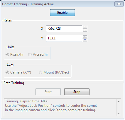
To enter the rate manually, you would select "Arcsec/hr" for units and
"RA/Dec" for axes, then enter the rates from the comet's ephemeris.
Comet rate training works like this:
First, center the comet in your imaging camera. If your imaging
application has some kind of reticle display, you should use that to
note the precise position of the comet on the imaging sensor. Once
this is ready, select a guide star in PHD2 and start guiding. Next
click "Start" in the Comet Tracking tool to begin training.
Take a continuous series of short exposures in your imaging camera
using your imaging application's Frame and Focus feature. Over time,
the comet will drift away from the starting location. Use PHD2's
"Adjust Lock Position" controls to move the comet back to the starting
location. You may have to experiment a bit to determine which way the
comet moves on the imaging camera sensor in response to the
Up/Down/Left/Right controls in PHD2. You may find it useful to enable
the "Always on top" button in the Adjust Lock Position window so the
controls stay visible on top of your imaging application.
PHD2 will quickly learn the comet tracking rate as you re-center the
comet. Once you are satisfied that PHD2 is tracking the comet, you can
click Stop to end the training. PHD2 will continue shifting the lock
position to track the comet until you disable comet tracking by
toggling the Enable/Disable button.
You can practice the comet training technique using the built-in
camera simulator. Check the "Comet" option in the Cam Dialog, and the
simulator will display a comet. Use a bookmark to mark the comet's
starting location, and use the Adjust Lock Position controls to move
the comet back to the bookmark location.
Guiding Assistant
The
Guiding Assistant is an instructional tool to help you measure
current seeing conditions and the general behavior of your mount and
guiding
subsystem. When it's run, it temporarily disables guiding output
and measures the ensuing motion of the guide star. This can help
you
see the high-frequency motions caused by seeing (atmospheric)
conditions. These cannot be corrected by conventional
guiding because they occur at a much higher frequency than you can
typically even measure. Trying to correct for them with conventional
guiding is often called "chasing the seeing" and usually leads to
poor results. Avoiding it is best accomplished by
setting a minimum-move level that will cause PHD2 to ignore most of
this high-frequency behavior. The Guiding Assistant can also show
you other behavior of your system such as overall drift
rates in right ascension and declination as well as peak-to-peak and
maximum-rate-of-change measurements in
right ascension,. While these things can usually be "guided out",
measuring them can be helpful if you want to improve the underlying
performance of the mount - for example, by improving your polar
alignment if the declination drift rate is high. The Guiding
Assistant can also measure the declination backlash in your system if
you select that option in the user interface.
When the Guiding Assistant is first started, you'll see a dialog box like this:
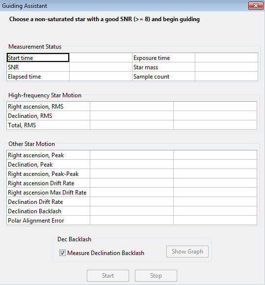
The
upper message area in the Guiding Assistant dialog box displays usage
instructions, much like a wizard interface. In order for the
Guiding Assistant to start measurement, you first need to start guiding
in the usual way. This identifies the target star in the frame
and enables (but does not start) the underlying data collection
mechanism. You then click
'Start' in the Guiding Assistant to begin the measurement process.
Once you do this, guiding commands will be disabled, so the star
will appear to wander around on the display - this is entirely normal.
As guider images are acquired, statistics are computed and
displayed in real-time in the user interface. Of particular interest
are the table entries in the "High-frequency Star Motion" section which
show ongoing results of the averaging process. After about one
minute of data collection, these numbers will usually stabilize and
you'll have a reasonable measurement of the high-frequency star
movement caused by seeing conditions. You'll also have a
reasonable measure of your polar alignment error although the accuracy
will generally improve if you let the sampling run for longer periods
of time. When you click the 'Stop'
button, this phase of the measurement process will stop. If
you've checked the box to 'Measure Declination Backlash" that process
will commence (see below). If not, guiding commands will be
re-enabled and the data collection
process will end. Other computed results will be displayed
in the lower area of the table showing overall drift rates and various
other measurements. All of these values are displayed in
units of both arc-seconds and pixels. The dialog box will look
something like this:
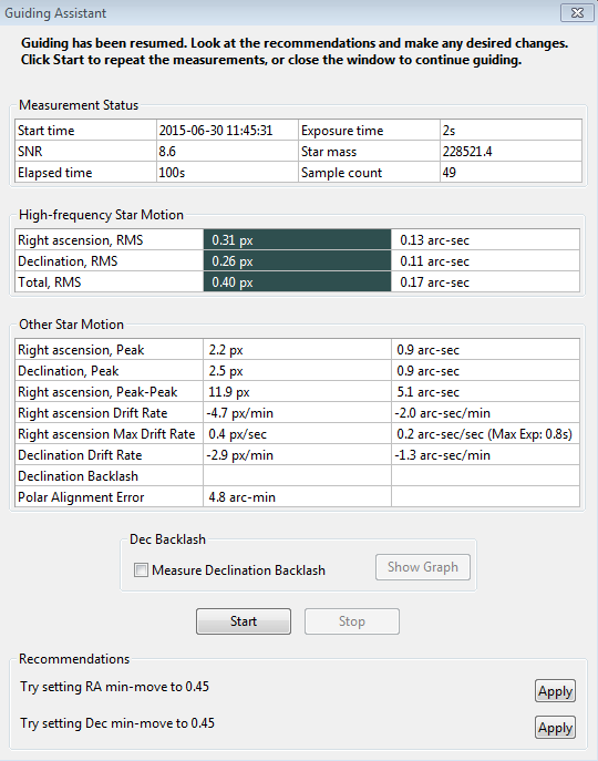
The
contents of the 'Recommendations' group at the bottom of the window
reflect the results of the high-frequency measurements. Assuming
your chosen guide algorithms support a minimum-move property, you have
the option of automatically setting those parameters based on the
results. You can also decide to re-run the measurements or close
the dialog box altogether if you want to proceed with normal guiding
operations.
Measuring Declination Backlash
If
you've checked the box to 'Measure Declination Backlash',
that process will begin as soon as the high-frequency measurements
are completed. In other words, clicking once on the 'Stop' button
halts the high-frequency measurements and begins the measurement of
declination backlash. A new group of status messages will be
shown immediately above the 'Start' and 'Stop' buttons so you can see
what's being done:
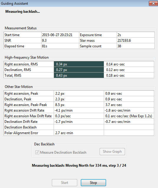
To
do backlash measurement, PHD2 will move the star by large amounts,
first in the north direction, then back to the south. There is
some risk the star will be lost during this process or the star might
already be too close to the north edge of the sensor. You
should choose a guide star that has plenty of room to move north
to get the best accuracy. If the star is lost because it's been
moved outside the search region, you can temporarily increase the size of that region from
the 'Guiding'
tab of the Advanced Settings dialog.
A search region size of 20 pixels should work for most
configurations - just be sure you don't have multiple stars inside the
search region. The first phase of backlash measurement involves
an initial attempt to clear whatever backlash is present in the north
direction. The Guiding Assistant (GA) will continue with these
clearing commands until it sees a significant and consistent movement
of the
guide star in one direction. Once this is done, the GA will issue
another sequence of commands to continue moving the star north by a
large amount.
This will take at least 16 seconds and may take longer depending
on the configuration - you can watch the status update to see what's
being done. When the north steps are finished, the GA will issue
an identical number of steps in the south direction. If there's
significant backlash in the mount, it may take a long time for the star
to start moving south, but that will usually be handled. Once the
south steps are done, regardless of how far the star has actually
moved, the backlash amount will be computed. However, if the star hasn’t moved at all in the south
direction, the computed backlash amount will be too small. At that point, you can know your declination
backlash exceeds 8 seconds, which is a very large amount.
The Guiding Assistant will then try to move the star back to its
starting position and will re-enable guiding. Again, there is
some risk the star may be lost, but this won't affect the calculations
- you can simply stop and resume guiding as you normally would.
Unlike the first process for measuring high-frequency star
movement, you don't need to click on the 'Stop' button once backlash
measurement has begun. The measurement process will terminate
when all the steps have been completed, and normal guiding will be
resumed. However, you can click on the 'Stop' button if something
has gone wrong - such as a lost-star condition - and then restart when
you're ready. When the backlash tests are finished, you'll see
the results
displayed as before, with the addition of entries for the amount of
declination backlash in units of both pixels and time (ms):
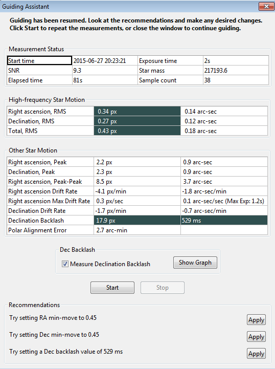
Depending
on the amount of backlash, you may see a recommendation for setting a
backlash compensation factor - 529 ms in the example shown above.
If the measured amount is less than 100 ms, no recommendation
will be made because such a small amount probably doesn't warrant any
compensation. If the backlash is very large, over 3 seconds,
you'll see a different recommendation to use uni-directional guiding in
declination. That's because trying to compensate for such large
values probably won't work very well, and the mount will probably not
be able to reverse directions quickly enough to support bi-directional
guiding. Obviously, you can reach your own conclusions based on your
experience with how the mount behaves. Before doing these
measurements, be sure to disable any backlash compensation that's previously been
enabled in the mount software. If this isn't done, the measurements and
any subsequent attempts at compensation by PHD2 will be invalid.
You
can look at a graphical display of the backlash measurement results to
get a better understanding of how the mount performed. Just click
on the 'Show Graph' button to see a graph that might look something like
this:
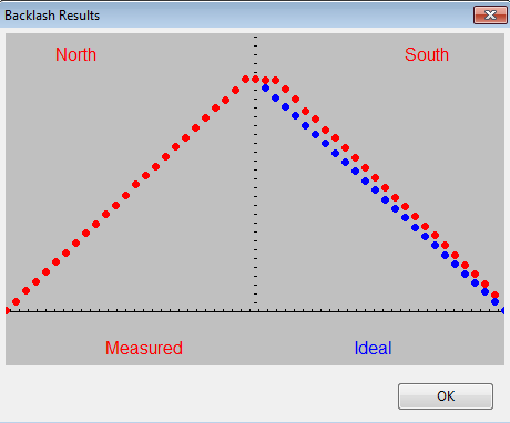
The
red points show the measured declination positions, shown left to
right, beginning with the north moves and ending with the south
(return) moves. The blue points show the south-return behavior
for a perfect mount with zero backlash. In this example, there is only a
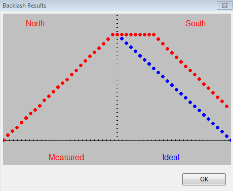
modest amount of backlash as evidenced by the flattened top of the red
points. However, the flattened top will be much more pronounced when
there is significantly more declination backlash in the mount, as in the following example:
Declination Backlash Compensation
Starting
with the 2.5 release, PHD2 supports a backlash compensation mechanism
that may help to improve mount performance when there is a
moderate amount of declination backlash. It is different from the
backlash compensation that's supported in some mount firmware
because the PHD2 implementation is adaptive.
The greatest risk with backlash compensation is that it will be
too large and will drive the mount into unstable oscillations in
declination. PHD2 will watch for this behavior and rapidly and
automatically adjust the compensation downward until the oscillation
disappears. Obviously, backlash compensation is applied only
when the direction of declination guiding is reversed. When you
first set a backlash compensation parameter with the Guiding Assistant
(recommendations section), you should give PHD2 some time to adjust it.
Let normal guiding proceed and watch for over-shoots in
declination. You can see these pretty easily by watching the
guiding graph with the option checked to show guiding corrections.
If you see some initial oscillation and instability in
declination, let guiding run for awhile to see if PHD2 can stabilize
the behavior.
The setting for backlash compensation is shown in the 'Algorithms' tab of the Advanced Settings dialog. The value shown there may be smaller than what was computed by
the Guiding Assistant if PHD2 had to adjust it downward. You can
modify this parameter directly if you want to experiment with it or you
can disable backlash compensation altogether using the adjacent
checkbox. Once you've measured the backlash a few times with the
GA and see a fairly consistent pattern of results, there's
probably no need to measure it every time you run the GA. Just
uncheck the 'Measure Declination Backlash' option until you want to
measure it again.
Managing Equipment Profiles
Equipment profiles were introduced in the section on Basic Use
where they are used as part of the 'Connect Equipment' dialog. If
you want to manage multiple profiles, you will probably want to use the
'Manage Profiles' button in the 'Connect Equipment' dialog. Using
the menu items there, you can create a new profile
or edit/rename/delete an existing one. Each profile holds
all the settings that were active at the time the profile was last
used. If you create a new profile, you can import these settings
from either the PHD2
generic defaults or from an existing profile. You can also use the
'Wizard' option to have PHD2 establish settings that are specific to
your equipment configuration. To
edit the settings in an existing profile, you first select it in the
equipment profile drop-down list, then click on 'Settings' under the
'Manage Profiles' pull-down. This will take you to the 'Brain'
dialog, where you can make whatever changes you want. Remember
than profiles are automatically updated anytime settings are changed
during a PHD2 session. Finally, you can import and export
profiles for purposes of debugging, backup, or even exchange with other
PHD2 users.
Advanced Settings for the Simulators
The device simulators were introduced in the Basic Use
section as useful tools for you to experiment with PHD2 and become
famliar with its features. Remember that you must choose
'Simulator' as the camera type and 'On-camera' as the mount type in
order to get the benefits of simulation. As you become more
interested in the details of the simulation, you can use the 'Cam
Dialog' button on the main display to adjust the simulation parameters:
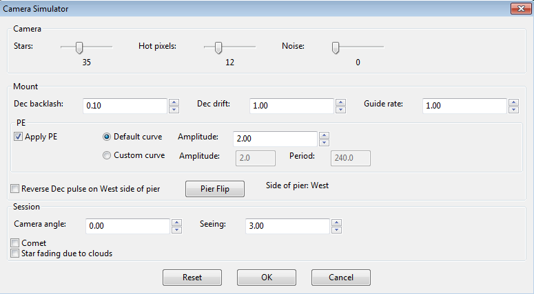
You can adjust simulated mount behaviors for declination backlash, drift
due to polar mis-alignment, and periodic error. You can also
adjust the 'seeing' level, which will create fairly realistic guide
star deflections that look like seeing effects. If you adjust
these parameters one-by-one, you'll see how they affect star
deflections and how the different guide algorithms react to those
movements. Of course, you're dealing with a "nearly perfect" mount in
these scenarios (except for backlash), so the simulation can't be entirely realistic.
Keyboard Shortcuts
Keyboard
shortcuts are available for many of the more commonly used tools and
functions in PHD2. These are enumerated in the Keyboard Shortcuts section.