Advanced Settings
Advanced settings are accessed by clicking on
the 'Brain button', a feature well-known to users of the original PHD.
PHD2 has a considerably larger set of parameters that can be
adjusted to optimize your guiding performance. Although these
are
called "advanced" settings, they are not particularly difficult to
understand, and you shouldn't hesitate to explore them. All
of
the fields on these forms include "tool tips", small message windows
that describe each field in some detail. Simply
"hover" the
cursor over the field to see the tool-tip. In many cases,
this
will provide all the information you need. Because there are
many more settings available, the Advanced Dialog in PHD2
is organized
into notebook tabs that are activated by clicking on the tab names.
All of the tabs share a common set of 'Ok' and 'Cancel' buttons
at the bottom of the form. Clicking on 'Ok' means that changes
made to any of the tab fields will be put into effect. Clicking
on 'Cancel' discards any changes that were made.
Global Tab
Camera Tab
Guiding Tab
Algorithms Tab
Other Devices Tab
Global Tab
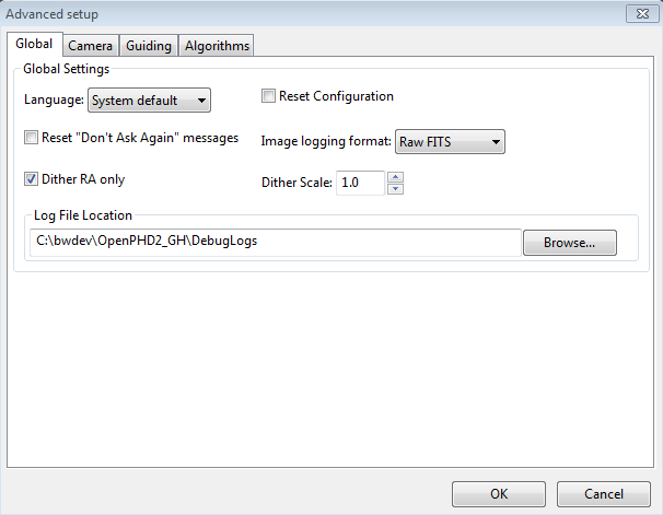
The controls on the
'Global' tab are well-described by their respective tool-tips, but they
are summarized here for completeness:
- 'Language' - determines the language
used in the PHD2 user interface, subject to available localization.
Changing this requires a program restart
- 'Reset Configuration' - restores all settings to their
initial values as if PHD2 had been freshly installed
- 'Reset Don't Ask Again messages' - restores the display of alert messages if you have previously chosen to not show them
- 'Image logging format' - specifies the file format if
star-image logging is enabled. If you are doing this for the purpose of documenting a problem, use Raw FITS
- 'Dither
RA only' - for imaging apps that use the PHD2 server interface,
specifies that dithering should be done only on the RA axis
- 'Dither scale' - an optional multiplier used to adjust the maximum-dither amount specified by the image application. See Dithering Operations
- 'Log File Location' - specifies a file directory where PHD2 guide and debug log files will be stored.
Camera Tab
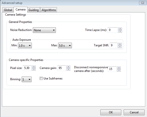
The controls on the 'Camera' tab are used as follows:
- 'Noise
reduction' - specifies the algorithm to use for handling noisy guide
camera images - those for which dark frames are not sufficient.
Choices include None, 2x2 mean, and 3x3 median. Both 2x2 mean
and 3x3
median will reduce the noise considerably. 3x3 median is especially
effective at removing hot pixels and neither will significantly affect
guiding accuracy. However, creating a bad-pixel map is
likely to be a better solution with less impact on your ability to
detect faint stars.
- 'Time lapse' - imposes a fixed delay between
guide exposures. This can be useful if the guide exposures
are
very short and you don't want to overload either the mount or the
camera
link with very high traffic rates.
- 'Auto Exposure' - these are the settings that control Auto exposure time.
- Min
Exposure - the minimum exposure time. PHD2 will not set the exposure
time
less than this value, even if the guide star SNR is higher than the
target SNR value.
If the min exposure time is set too low, you are likely to chase seeing
effects and thereby get poor guiding results. Users of AO
units will usually set this to a lower value, since rapid small
corrections are often
desirable with an AO.
- Max Exposure - the maximum exposure time. Before a guide star is selected, PHD2
will set the exposure time to the maximum value. Once a guide star is selected, PHD2
will then incrementally decrease the exposure time until the desired SNR is reached.
- Target SNR - this is the average SNR value that PHD2 will attempt
to achieve
by adjusting the exposure time. SNR can fluctuate from frame to frame
even with a
fixed exposure duration, so be sure to account for that when choosing a
target SNR
value. PHD2 will reject frames when SNR drops below 3.0. The default
value of 6.0
should provide enough of a cushion to prevent fluctuations from causing
the SNR to
go below 3.0. As mentioned in the 'Basic Use' section, SNR is
similar but not identical to the signal-to-noise ratio used in
photometry.
- 'Pixel
size' - The guide camera pixel size in microns. This is the second of two parameters needed by PHD2
to compute the
guider image scale and thus report guider statistics in units of
arc-seconds. The other
parameter required for this is the guide scope focal length, located on
the
'Guiding' tab. Refer to your camera documentation to determine
the
correct value for pixel size. If your camera has non-square
pixels, just choose one of the dimensions or input the average of the
two. The pixel size has no effect on guiding accuracy, so a small
amount of imprecision in the user interface won't cause any
problems.
- 'Camera
gain' - Sets the gain level for the many cameras
that support this feature. Reducing this parameter can help to
reduce the noise level or may allow use of a bright star without
saturation.
- 'Disconnect
nonresponsive camera after (seconds) - Camera malfunctions will
sometimes occur, often because of faulty USB connections. In many
cases, the camera will not return the requested image data, and PHD2
will appear to "hang." This parameter determines
how long PHD2 should wait for a response after the expected exposure
time has expired. For example, a timeout value of 5 seconds in
conjunction with an exposure time of 2 seconds will tell PHD2 to wait
up to 7 seconds for a response. If the data are not received
within that period, PHD2 will attempt to halt the operation, disconnect
the camera, and display an alert message in the main window.
Since a hardware problem is likely the underlying issue, this
recovery attempt won't always succeed. You should be
generous with these timeout values to avoid spurious recovery
actions. Also, if you are using a guide camera that shares
electronics with the main imaging camera, you should set this timeout
to a large
value, well above the maximum expected time for a full-frame download
from the main imager. This is a consideration for users of
the SBIG driver that is packaged with Sequence Generator Pro.
Regardless of whether PHD2 is able to handle the situation
gracefully, the underlying problem is almost certainly in the
hardware or the camera driver and will need to be resolved before
guiding is continued.
- Binning
- for those cameras that support on-chip (hardware) binning, you can
specify the binning that will be used while taking guide exposures.
See below for a more detailed discussion.
- 'Use subframes' - For cameras that support this
feature, PHD2
will download only a 100x100 subframe of each guide
exposure. This is very useful for cameras with slow download
times, allowing them to be used more effectively for guiding.
This feature applies to both calibration and guiding.
During initial looping without a selected star, the full
frame is downloaded, but once a star is selected, only this small
subframe is downloaded. If you are using subframes but want to
see the full frame to select a different star, just click anywhere
outside the subframe.
Use of Binning
Some
of the guide cameras available in PHD2 support hardware-level binning,
and this may be helpful in situations where you are guiding at
long focal lengths or have a guide camera with very small pixels. These
scenarios often result in having to use faint guide stars, and the
guider images may be substantially over-sampled. Over-sampling
provides no real benefit, and the projection of a faint star disk onto
many small pixels can result in a low signal-to-noise ratio (SNR).
By binning the image, you can reduce the impact of camera read
noise and thus improve the SNR; and if you are over-sampled, you
won't degrade the accuracy of computing the guide star location.
Choosing a binning factor greater than one will have the
following effects:
- Star images will have a higher SNR and
will be easier to detect above the background noise level. This
is only beneficial if you are limited to a choice among faint stars
(i.e. with SNR values near the threshold of 3).
- The amount of
data downloaded from the camera will be reduced by the square of
the binning factor. This can be helpful if you are using a camera
that makes heavy use of USB resources even if star brightness and
SNR are already reasonable with un-binned images. Of course,
using sub-frames can achieve the same result once a star has been
selected.
- The resolution (image scale) of your guider image
will be reduced by the binning factor. This is not likely to be a
problem if the un-binned image scale is below 1 arc-sec/pixel, but your
guiding results may suffer if the un-binned image scale is well above 1
arc-sec/pixel. You may need to experiment because the results
will also depend on the image scale of your main camera system.
- Each
binning level requires its own dark frames and bad-pixel map -
they are not interchangeable, nor can a transform be done
automatically. If you foresee the need to switch back and forth
between binning settings, you should create separate profiles for each
setting. Then build a dark library and a bad-pixel map for
each of those profiles. When you want to change binning factors,
just switch to the profile that has the setting you want, and a dark
library and/or bad-pixel map will be available.
Most PHD2
users probably won't need to use binning, and you should probably avoid
doing so unless you have a clear understanding of the implications and
an equally clear idea of what you are trying to accomplish.Guiding Tab
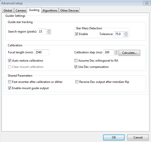
The
guiding tab shows the parameters used for calibration,
star-tracking, and guiding behavior shared by all of the guide algorithms..
Guide Star Tracking
- 'Search
region' - specifies the size of the "tracking rectangle", in units of
pixels. You may need to increase this value if your mount
does
not perform well or, more commonly, if it's not well-aligned on the
celestial
pole. You may also want to increase it temporarily while using
the Guiding Assistant so that backlash measurement can be done without
losing the guide star. Just remember that an overly large search
region also increases the likelihood that multiple stars will live
within its boundaries, which could lead to guiding problems.
- 'Star mass detection' - tells PHD2 to monitor the
brightness and size of the guide star compared to the sky background.
- 'Star mass tolerance' - if the 'Enable' box
is checked, PHD2 will trigger a 'lost star' error if the measured
brightness and size vary by more than this percentage. This
might be useful if you have two stars inside the tracking rectangle and
you want to be sure PHD2
doesn't mistakenly switch stars.
It can also
prevent errors caused by thin clouds, high camera noise, or alpha
particle artifacts;
but it may be unreliable if you are guiding on a faint star. If
you are getting too many 'lost star' errors when the star is plainly
visible on the display, try increasing the value of this setting.
Resetting the 'Enable' checkbox or setting the threshold to 100 will disable the warnings
entirely.
Calibration
- 'Focal length' - the focal length of the guide scope (millimeters). This provides one of
two parameters needed by PHD2 to compute the image scale and thus
report guiding performance in units of arc-seconds. The other
parameter required for this is the guide camera pixel size, located on the
'Camera' tab.
- 'Calibration
step-size' - specifes the duration of the guide pulse that
PHD2
will use during calibration. Its use is described in the
'Auto
Calibration' section of the 'Basic Use' help page. You can
adjust
the value depending on whether the guide star is moving too quickly
or too slowly during calibration. As a general guideline, it
is
good to calibrate within about 30 degrees of the celestial equator
(declination = 0), and to use a calibration step size that will result
in 8-14 steps in each direction. The 'calculate...' button
to
the right of this control will launch a dialog that can help you
compute an appropriate value (see below)
- 'Auto restore calibration' - tells
PHD2 to automatically reload the most recent calibration data as soon
as the equipment is connected. Be sure to read the Auto calibration section to understand the implications
and potential risks of doing this.
- 'Assume
Dec orthogonal to RA' - Normally, the calibration process independently
computes the camera angles for both right ascension and declination.
There is no need for great precision on these values, and the
default behavior normally works well. However, if your mount has
very high periodic error or you are dealing with very bad seeing
conditions, you may want to force the RA and Declination angles to be
perpendicular. If you choose that option, PHD2 will compute the
camera angle for RA, then assert a declination angle that is orthogonal
to it.
- 'Clear mount calibration'
- tells PHD2
you want to clear the calibration data currently being used for the mount and
re-calibrate
before
guiding is restarted. You might do this for a variety of
reasons
- you might have rotated the guide camera or slewed to a target close to the celestial pole, etc.
You can also accomplish the same result by doing a Shift-Click on
the guiding icon on the main page, which will force a re-calibration.
- 'Use
Declination Compensation' - if PHD2 can get pointing information from
the mount via an ASCOM connection ('Mount' or 'Aux'), it will
automatically adjust the RA guide rate based on the current declination.
This box should normally be left checked except in very unusual
cases. For example, SiTech mount controllers evidently apply a
compensation automatically, in which case PHD2 should not.
Shared Guiding Parameters- 'Fast
re-center after calibration or dither' - during calibration or
dithering, the mount may be moved a significant distance from the
initial "lock" position. If you click this checkbox, PHD2 will
move the mount back to the lock position as quickly as possible,
using the largest guide commands permitted by the 'Max Duration' settings of
your guide algorithms. This is only an optimization, so the use
of this checkbox is completely optional.
- 'Reverse Dec
output after meridian flip' - tells PHD2 how to adjust the
calibration data after a meridian flip. Some
mounts track their 'side of pier' state and automatically reverse the
direction of guide commands in declination. Other mounts do not do this. In either case, PHD2 needs to know if
the
mount will automatically change its behavior based on
side-of-pier. You may have difficulty finding information about
how your mount behaves in this respect, so it's probably easiest to
just run a quick experiment. With the checkbox disabled,
calibrate on one side of the pier, then move the mount to the other
side. Select 'Flip Calibration' under the 'Tools' menu, and
start guiding. If the guiding works normally, leave the box
un-checked; but if you see run-away in declination, check the box and
repeat the entire procedure, including calibration.
- 'Enable
mount guide output'
- this is normally checked because it tells PHD2 to send guide
commands to the mount. But there are some
circumstances
where you might want to disable this, usually because you want to
observe the uncorrected behavior of the mount. For example,
you
can disable guider output in order to see the general shape and
amplitude of your mount's periodic error or to check the amount of
drift from polar mis-alignment.
- 'Stop
guiding when mount slews' - if guiding through an ASCOM interface, PHD2
can detect that a slew operation is underway and will stop issuing
guide commands..
Calibration Step Calculator
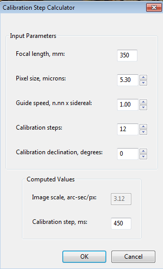
To
use the calculator,
be sure the topmost three edit controls are
correctly filled in. If you have already specified the focal
length and
the camera pixel size in the 'Global' and 'Camera' tabs respectively,
those fields will already be populated in this form. If you are
using an ASCOM connection to your mount, the fields for "Guide speed"
and "Calibration declination" will also have the correct values.
Otherwise, you'll need to supply them yourself. The guide
speed is specified as a multiple of sidereal speed - most mounts will
use something
like
1X or 0.5X sidereal, but you can choose something else. You
can
leave the 'calibration steps' field at the default value of 12, which
is likely to result in a good calibration. Use of a significantly
smaller value raises the likelihood that seeing errors or small mount
errors will cause calibration errors . As you change the values
in these fields, PHD2
will recalculate your current image scale and a recommended value for
the
calibration step-size. If you then click on 'Ok', that value
will
be inserted into the calibration step-size field of the 'Guiding' dialog.
Clicking 'Ok' will also populate the focal length and camera
pixel size fields in the 'Guiding' and 'Camera' tabs, so any changes you
made in the calculator will be reflected there as well. However,
this will not be done if you click on 'Cancel' in the calculator
dialog. Note that PHD2 never changes the guide speed setting in
your mount regardless of what may be entered in the 'Guide Speed' field.Algorithms Tab
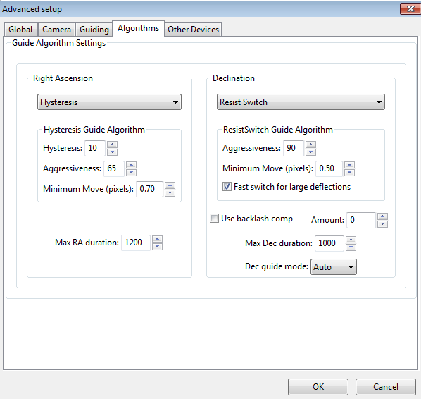
The algorithms tab can be used to select the guiding algorithms you
want to use and to fine-tune the parameters associated with them. The parameters displayed will change significantly if
you
change the algorithm selections. For that reason, all the
parameters related to guide algorithms will be treated together, in a
separate section.
The remaining controls, the ones that are independent of the guiding
algorithm selections, are described below.
- 'Max RA duration' - specifies the maximum allowed
guide pulse duration for right ascension. You might reduce
this
below the default value if you want to avoid chasing a large
deflection that could be caused by a spurious event (e.g. wind gust, hot pixel, etc.) .'
- 'Use backlash comp' - this
controls whether PHD2 will apply a compensation factor when the
direction of declination guiding needs to be reversed.
Measurement of backlash and calculation of a good starting value
for the compensation factor is done in the Guiding Assistant. The
size of the additional guide correction (compensation value) is shown
in the 'Amount' field adjacent to the checkbox. This amount may
be adjusted downward by PHD2 if necessary to avoid over-shooting and
oscillation. Since
PHD2 has the ability to detect and adapt to over-corrections, the
backlash compensation available here should work better than the
fixed backlash compensation available in many mount controllers.
If you use the PHD2 backlash compensation, you should disable
any backlash compensation in the mount. See the help section on the Guiding Assistant for more details.
- 'Max Dec. duration' - specifies the
maximum allowed guide pulse duration for declination (same as above but
for declination).
- 'Declination guide mode' - gives you additional control over declination
guiding. Declination guiding is not like RA guiding because the
errors are not caused
by imperfections in your mount's gears. Instead, deflections in
declination are primarily the result of imperfect polar alignment or flexure.
The result is an error that should be smooth and mostly uni-directional, assuming there is no over-shoot from an
earlier correction. The default value of 'auto' tells PHD2 that
some reversals in direction are acceptable, subject to the behavior of
the various guiding algorithms. However, if your mount has severe
declination backlash, you may want to prevent direction reversal
altogether. If so, you can select either 'north' or 'south' to
restrict corrections to only that direction. Keep in mind,
however, that an over-shoot in correction with one of these modes
will leave the star positoned off-target for an extended period of
time. So you'll probably want to use conservative parameters for
aggressiveness if you are disallowing direction reversals.
Finally, a choice of 'none' here disables declination guiding
altogether.
Other Devices Tab
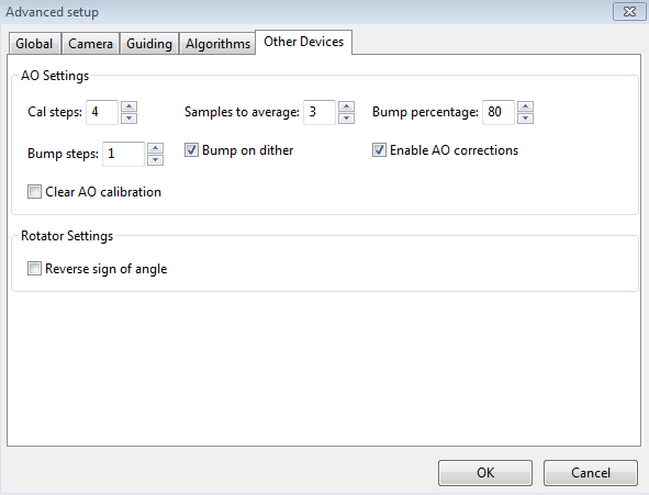
If
you are using either an adaptive optics or rotator device, the "Other
Devices" tab will be shown. The upper section deals with the AO
device if one is being used. You
can use the first four parameters to control the
calibration process and the manner in which 'bump' operations are done.
The 'calibration step' field tells PHD2 the amount to move the
tip/tilt element in each of the up/down/left/right directions, in
units of AO steps, during calibration. The guide star position is measured at the
beginning and end of each leg of the calibration, and the 'samples to
average' parameter tells PHD2
how many samples to take at each of these
points. Averaging images is important because the seeing will
always cause the guide star to "bounce around" a bit. As
discussed earlier, the AO unit can make corrections
only within a limited range of guide star movement. You
will want to initiate mount 'bump' corrections before these limits
are actually reached, and the 'bump percentage' field is used for that
purpose. To move the mount, the full bump correction is
accomplished in steps - the 'bump step' field controls the size of
these increments. If the bump operation has begun and the guide
star remains outside the "bump percentage" area, PHD2
will increase the
bump size until the guide star is back within that range.
Additional movement from that point to the center position will
continue at the specified "bump step size". This complexity is
required in order to maintain good guiding, with no elongated stars,
even as the mount is being bumped. During the bump operation, the
AO is continuing to make corrections, so the long "mount bump" is
continuously offset by adjustments in the AO.
The
'Bump on dither' option tells PHD2 to bump the mount when a dither
command is received and thus move the guide star back closer to the
center position of the AO. The
option to enable or disable AO guide commands operates independently
from the 'Enable mount guiding' checkbox in the Guiding tab. So
you can
independently enable/disable either the guide commands to the tip/tilt
device or the
'bump' guide commands to the mount. The same principle holds for
the 'Clear AO calibration' option - that will force a recalibration of
the AO without affecting calibration of the mount.
When an AO is in use, the 'Algorithms' tab will only show choices for controlling the tip/tilt optical element in the AO
device
itself.
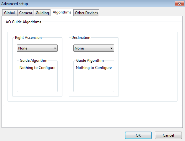
Since
the
AO is not trying to move a heavy piece of equipment, you can
afford to be more aggressive in your guide algorithm choices.
The default algorithms for an AO are 'None', which means
there will be
no damping or history-based calculations applied at all. In that
case, each correction will be based only on the most recent guide frame
and will make a 100% correction of the most recent deflection. If
you use a different algorithm, you should
probably start with a high level of aggressiveness there as well,
perhaps 100%.
The other, shared guiding parameters normally displayed on the
'Algorithms' tab will not be shown for the AO because they aren't used
to control the device.
The rotator device has only
one parameter, which lets you match the behavior of the device to the
ASCOM notion of positive and negative angles. The "Reversed"
checkbox can be used for
optical systems that reverse the image, usually because they have an odd number
of mirrors. The direction and amount of rotation is used to
adjust the calibration data, so PHD2 follows the ASCOM standard:
"the rotator position is expressed as an angle from 0 up to but
not including 360 degrees, counter-clockwise against the sky."
Experimentation is likely to be the quickest way to determine if
the box should be checked.